- DNOW Affiliated Brands
- Colorado Seals
Colorado Seals
Colorado Seals, a DNOW Company, is a regional expert offering mechanical seals, gaskets, seal repair services, seal surveys and seal failure analysis in Colorado and the surrounding areas. We utilize our suppliers’ extensive technical and engineering abilities to provide you, our valued customers, with the best experience in the industry.
Your Partners in Reliability
Strong Relationships Through Support
Supporting U.S. Industry and U.S. Products
Exceptional Customer Service
Colorado Seals Product Lines
Colorado Seals understands that all our clients’ inquiries are urgent and of top priority. We are committed to offering 24/7 customer service support to ensure all your business needs are serviced immediately. We specialize in rotating equipment, mechanical seals, packing, industrial pumps and related equipment, and we are stocking distributors for most products.
- Mechanical seals
- Bearing isolators
- Gaskets
- Filtration products
- Braided and injectable packing
- ANSI pumps and parts
- AODD pumps
- Positive displacement pumps
- Vertical turbine pumps
- Disc pumps
- Horizontal pumping systems
- Industrial lubricants and coatings
- Pipe connectors
- Shims



Colorado Seals Services
In addition to top-quality products, Colorado Seals has the tools and expertise to offer superior services. Our outside sales representatives are happy to schedule a visit to provide knowledgeable and meaningful support.
- Seal repairs for most manufacturers
- Seal failure analysis reports
- System reliability diagnosis
- Plant surveys and location visits
- Product recommendations
- In-person training courses
Seal Repair Shop
Colorado Seals repairs all types of damaged mechanical seals to “like new” condition, quickly and at a reasonable cost. The answer to your sealing problems is not always a new seal – it’s a better repair service!
- All seal makes and manufacturers
- Cost effective analysis for seal repair or replacement
- Material upgrade installation
- Surplus and reconditioned seals available
Seal and Pump Training
Our one-day course provides a foundational understanding of mechanical seals and centrifugal pumps, presented by seasoned veterans with over 75 years of combined experience.
- Learn current techniques and products for increasing MTBF
- Learn seal and pump operation principles
- Receive a complete training manual
- Schedule on- or off-site presentation
Contact Colorado Seals
We are dedicated to serving our customers in Colorado and the surrounding areas. Please visit our address in Centennial, Colorado or give us a call or email. We are here for you!
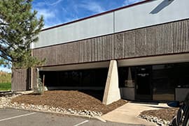
Centennial (Colorado Seals)